1. Before assembly, ensure that there are no foreign objects on the surface of the shaft sleeve and seat hole, and the surface of the seat hole should be as smooth as possible to avoid scratches during assembly
2. During assembly, lubricating oil can be applied to the outer surface of the shaft sleeve to facilitate its installation, but it should not be too much to prevent the shaft sleeve from detaching during heavy loads or reciprocating movements
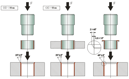
3. During assembly, the core shaft should be slowly pressed in (it is recommended to use an hydraulic press), and direct tapping of the shaft sleeve is prohibited to avoid deformation
When designing the seat hole, if it is necessary to use easily deformable materials such as aluminum alloy or if the wall thickness of the seat hole is relatively thin, please explain to avoid deformation of the seat hole during pressing
5. In order to make assembly simpler and not damage the wear-resistant layer, the end face of the shaft must have rounded chamfers. The material of the shaft is recommended to be bearing steel surface quenched HRC45, with a surface roughness of Rz2-3, and the surface can also be plated with hard chromium.
Inspection method for shaft sleeve
1. Outer diameter: The GO and NO GO methods are used, with the GO end being the maximum outer diameter and the NO end being the minimum outer diameter
2. Inner diameter: Press the shaft sleeve into the reference hole (H7 middle value tolerance) and use a cylindrical plug gauge to inspect the shaft sleeve. The through end of the plug gauge is the minimum size of the shaft sleeve inner hole, and the stop end of the plug gauge is the maximum size of the shaft sleeve inner hole. The accuracy level of the inner hole of the general rolling type shaft sleeve is H9
3. The dimensions of the ring gauge and plug gauge shall be in accordance with the DIN 1494 emblem shaft section.